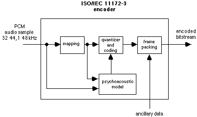
Figure 1 -- Sketch of the basic structure of an encoder
ISO/IEC 13818 was prepared by SC29/WG11, also known as MPEG (Moving Pictures Expert Group). MPEG was formed in 1988 to establish a standard for the coded representation of moving pictures and associated audio stored on digital storage media.
This Recommendation International Standard is published in three parts. Part 1 - systems - specifies the system coding layer of the standard. It defines a multiplexed structure for combining audio and video data and means of representing the timing information needed to replay synchronised sequences in real-time. Part 2 - video - specifies the coded representation of video data and the decoding process required to reconstruct pictures. Part 3 - audio - specifies the coded representation of audio data and the decoding process required to decode audio signals.
This part is based on ISO/IEC 11172-3 "Coding of moving picture and associated audio for digital storage media at up to about 1,5 Mbit/s".
To aid in the understand of the specification of the stored compressed bitstream and its decoding, a sequence of encoding, storage and decoding based on ISO/IEC 11172-3 document is described.
Figure 1 -- Sketch of the basic structure of an encoder
There are four different modes possible, single channel, dual channel (two indepenten audio signals coded within one bitstream), stereo (left and right signals of a stereo pair coded within one bitstream), and Join Stereo (left and right signals of a stereo pair coded within one bitstream with the stereo irrilevancy and redundancy exploited).
Layer I
This layer contains the basic mapping of the digital audio input into 32 subbands, fixed segmentation to format the data into blocks, a psychoacoustic model to determine the adaptive bit allocation, and quantization using block companding and formatting. The theoretical minimum encoding/decoding delay for Layer I is about 19 ms.
Layer II
This layer provides additional coding of bit allocation, scalefactors and samples. Different framing is used. The theoretical minimum encoding/decoding delay for Layer II is about 35 ms.
Layer III
This layer introduces increased frequency resolution based on a hybrid filterbank. It adds a different (nonuniform) quantizer, adaptive segmentation and entropy coding of the quantized values. The theoretical minimum encoding/decoding delay for Layer III is about 59 ms.
Joint Stereo coding can be added as an additional feature to any of the layers.
Access to storage may involve remote access over a communication system. Access is assumed to be controlled by a functional unit other than the audio decoder itself. This control unit accepts user commands, reads and interprets data base structure information, reads the stored information from the media, demultiplexes non-audio information and passes the stored audio bitstream to the audio decoder at the required rate.

Figure 2 -- Sketch of the basic structure of a decoder
[ Index | Next Paragraph ]