Goffredo Haus, editor
Fall 1995
© IEEE Computer Society Press.
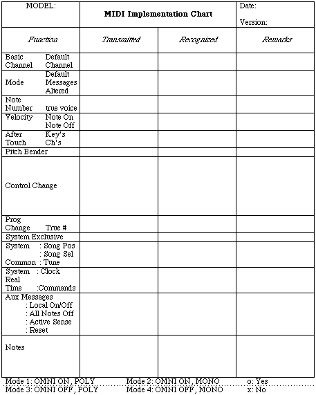
Instructions for MIDI Implementation Chart
The standard MIDI Implementation Chart is used as a quick reference of transmitter and receiver functions so that users can easily recognize what messages and functions are implemented in the instrument. This chart should be included in the users manual of all MIDI hardware products. For example, if a user intends to connect two MIDI instruments, they might compare the "Transmitted" part of one instrument's chart, with the "Recognized" part of the other instrument's chart by overlapping them. For this reason each chart should be the same size and have the same number of lines.
General
- 1) The "[ ]" brackets at the top of the chart is used for the instrument's name such as, [LINEAR WAVETABLE SYNTHESIZER].
- 2) The item "MODEL" should be used for the model number, such as "LW-l".
The body of the implementation chart is divided into four columns. The first column is the specific function or item, the next two columns give information on whether the specified function is transmitted and/or received, and the fourth column is used for remarks. This last column is useful to explain anything unique to this implementation.
Function Description
1. BASIC CHANNEL:
- a. Default: Channel which is assigned when power is first applied to unit.
- b. Changed: The channels which can be assigned from the instrument's front panel.
2. MODE:
- a. Default: This is the channel mode used by a Transmitter and Receiver when power is first applied. This should be written as Mode x (where x is 1 thru 4), as shown on the bottom of sheet.
- b. Messages: These are the mode messages which can be transmitted or received, such as OMNI ON/OFF, MONO ON, and POLY ON. MONO ON and POLY ON may be written in the short form "MONO", "POLY".
- c. Altered: This shows the channel modes which are not implemented by 8 receiver and the modes which are substituted. For example, if the receiver cannot accept "MONO ON" mode, but will switch to "OMNI ON" mode in order to receive the MIDI data, the following expression should be used: "MONO ON > OMNI ON" or "MONO > OMNI".
3. NOTE NUMBER:
- a. Note Number: The total range of transmitted or recognized notes.
- b. True Voice: Range of received note numbers falling within the range of true notes produced by the instrument.
4. VELOCITY:
- a. NOTE ON/NOTE OFF Velocity is assigned either an "o" for implemented or an "x" for not implemented. In the space following the "o" or "x" it may be mentioned how the Note On or Off data is being transmitted.
5. AFTERTOUCH:
- a. AFTERTOUCH is assigned an "o" or an "x" in the same manner as Velocity.
6. PITCH BENDER:
- a. PITCH BENDER is assigned an "o" or an "x" in the same manner as Velocity.
7. CONTROL CHANGE:
- a. Space is given in this area for listing of any implemented control numbers. An "o" or "x" should be placed in the appropriate Transmitted or Recognized column and the function of the specified control number should be listed in the remarks column.
8. PROGRAM CHANGE:
- a. The implementation of "Program Change" messages is indicated with "o" or "x" If implemented, the range of numbers should be included.
- b. True # (Number): The range of the program change numbers which correspond to the actual number of patches selected.
9. SYSTEM EXCLUSIVE:
- a. The implementation of"System Exclusive" messages is indicated with "o" or "x". If it is assigned an "o" a full description of the instrument's System Esclusive implementation should be included on separate pages.
10. SYSTEM COMMON:
- a. The implementation of "System Common" messages is indicated with an "o" or an "x".
- b. The following abbreviations are used:
- Song Pos stands for Song Position
- Song Sel stands for Song Select
- Tune stands for Tune Request
11. SYSTEM REAL TIME:
- a. The implementation of "System Real Time" messages is indicated with an "o" or an "x".
- b. The following abbreviations are used:
- Clock stands for Timing Clock
- Commands stands for Start, Continue and Stop
12. AUX. MESSAGES:
- a. The implementation of "Aux. messages" messages is indicated with an "o" or an "x".
- b. The following abbreviations are used:
- Aux stands for Auxiliary
- Active Sense stands for Active Sensing
13. NOTES:
a. The "Notes" column can be any comments such as:
- 'Power Up messages transmitted, implementation of program
- changes to additional memory banks, etc.'

Table XXI
[Index |
Main Paragraph ]