
System Common messages are generally intended for use with master controllers, drum machines and sequencers. There are five System Common messages. Their status word value and description are shown in Figure 1.2.1-1.
Figure 1.2.1-1 System Common Messages Status Values
The MIDI Time Code Quarter Frame (MTC) is used to synchronize devices. There are three types of MTC messages, Quarter Frame, Full and SMPTE (Society of Motion Picture and Television Engineers) time code User Bits.
Time code in LTC is typically given in BCD. One may be tempted to used 10*tens place + ones place in the computation of the BCD to binary (which is quite valid). A faster way is available to both the software and hardware designer. For example, in a trade of space for time, the software designer might be tempted to create a 7 by 9 array. The first index can be used for the 10's place and the second index for the one's place. This look-up table can be pre computed and placed into memory using a variety of languages (i.e., C, Pascal, LISP, FORTRAN, etc.). If the array consists of byte elements, then 79 bytes are needed. This is a amount of memory is available on all but the smallest of microcontrollers and PLD's (Programmable Logic Devices). The 68HC11A8P1 microcontroller, described later, has 512 bytes of EPROM, so this represents 15% of available memory.
Typically, we can view the BCD to binary conversion as follows:
The technique of comparison and addition is often reduced to a computed goto when a compiler is optimizing the case statement (this is also true for C's switch statement). This technique is faster than
I = one's_digit + 10 * tens_digit;on most computers (though less compact and less general).
To perform this type of computation very quickly, it may be necessary to use hardware. One HDL (Hardware Description Language) is called ABEL. Using the ABEL description, the SMPTE to binary converter is implemented using a truth table. The ABEL for this process is shown in Figure 1.2.1-2.

Figure 1.2.1-2 ABEL HDL for the SMPTE BCD PLD
The Programmable Logic Device may be programmed using a variety of techniques. Figure 1.2.1-3 shows VHDL (a variant on the ABLE HDL) with a sample PLD. Given a larger PLD, it should be possible to implement many MIDI functions (like routing and channel merging) in real-time [Mahmood 1995].


Figure 1.2.1-3 VHDL for the SMPTE BCD PLD
This is the same function as that shown in Figure 1.2.1-2.
The HDL implementation can yield a solution which can be computed in 3 gate delays (which is typically between 1-30 NS, depending on technology used).
Video signals are typically classified into two groups, progressive (non-interlaced) and interlaced. Progressive is typically found in computer displays and AT&T/Zenith 787 type HDTV. Interlaced video is found in most other types of video (PAL, SECAM, NTSC, MUSE, etc.). For video in the U.S.A. (NTSC) there are about 30 frames displayed in a second. Each interlaced frame contains an odd and an even field. In order to assist in the post-production process, a technique is needed which identifies every frame on a video tape. This gave rise to the SMPTE/ANSI time code. This time code comes in two forms, longitudinal time code (LTC, pronounced Lit See) and vertical interval time code (VITC, say VIT See). Both of these codes may be recorded on an audio track since they have a bit rate budget of 2,400 bits/second. It is typical, however, for LTC to be recorded onto the audio track of a video cassette recorder (VCR) and for VITC to be recorded onto the vertical interval. Some VCR's (like Sanyo's computer controlled S-VHS GVR-S950) only read and generate LTC. Others (like Sony's BetaCam BVW-75) will read and generate both.
The audio track may be on a video tape, a single track of a multi-track audio machine, or both. It is typical for a time code track on a multi-track machine to be used to sync electro-acoustic instruments with MIDI instruments. When this is done, the self-clocking time codes permit the linear change in tape speed to alter the rate at which the sequencers run. The result is that the analog audio tracks shift in frequency and playback rate, while the MIDI instruments shift only in playback rate.
LTC code is divided into 80 bits: 26 for identifying hours, minutes, seconds and frame number; 1 for identifying color phase; 1 for identifying dropped frames; 32 for user ID; 16 for sync (which signals the end of a time-code word) and 4 undefined. Initially, NTSC was a monochrome system with a frame rate of 30 Hz. In 1954 NTSC was retrofitted with color. At this time the frame rate was changed to 29.97 Hz and took the name "drop-frame". The conversion from 30 Hz to 29.97 Hz causes 108 frames to be dropped per hour. This is implemented by skipping two frames on the tape counter at the end of each minute, except for every tenth minute. VITC is a 90 bit code. The extra 10 bits provide error checking and field ID [Inglis 1993].
The LTC code is described in Figure 1.2.1-4.
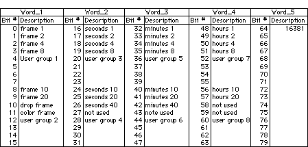
Figure 1.2.1-4 SMPTE LTC Format
The LTC is divided into groups of 4 bits. They may be regrouped into any multiple of 4 bits, with relative ease. Here we see the 80 bit code described by five 16 bit words (an unsigned short int, in C).
Word_5 contains the final sixteen bits of the 80-bit LTC and are called the sync word. The pattern is unique and serves as a flag which can be read during shuttle of a tape. It cannot be read if the tape is still. If VITC is recorded in vertical interval, it is readable without linear tape motion. A Binary Coded Decimal (BCD) coding scheme is used for the number of frames, seconds, minutes and hours. This means that, for example, if bits 8 and 9 could be extracted from Word_1, multiplied by 10 and added to an integer which contains bits 0 through 3 we would get a binary representation of the number of frames.
While some languages (like C) have the feature of being able to directly manipulate the internal bit representations of an integer, other languages (like Pascal) do not. The most general description of how to read the 80 bit LTC is therefore based on features which are available on most languages (like DIV and MOD). While the beginning C programmer may be tempted to used a field based struct, this cannot result in a portable implementation. Almost everything about fields is implementation dependent [Kernighan and Ritchie]. The programmer has a large number of techniques available for decoding LTC. For example, Since MIDI is byte oriented, why not break the LTC into bytes? This could be done by reading the data into a packed array of char (available in C and Pascal). With bitwise operations in C, this may be an easy alternative, however, without the bitwise operations in Pascal, this alternative will require system dependent subroutine calls and will be non-portable. These portability considerations (between platforms and languages) have led to a DIV and MOD based description of the bit manipulations.
Quarter Frame messages allow the transmission of the frame, seconds, minutes and hours which have elapsed on a video tape. There are two Quarter Frame messages for each field of interlaced video. A Quarter Frame message is two bytes long. The status word is the first byte. The second byte is computed using addition, truncated integer division (DIV) and the remainder operation (called modulo or MOD). DIV and MOD are operators in Pascal. They correspond to '/' and '%' in C. A number MOD 16, for example, is the least significant 4 bits. A number DIV 16 is the most significant 4 bits shifted to the right 4 times. This is shown in Figure 1.2.1-5.

Figure 1.2.1-5 Quarter Frame Message Types in MTC.
(SMPTE Type) * 2 causes a left shift by 1 bit. Offset is the message type * 16. There are 4 types of SMPTE time code, 0 = 24 fps (frames per second), 1= 25 fps, 2= 30 fps (drop-frame) and 3 = 30 fps non drop-frame. Film typically runs at 24-frames-per-second. Some countries use 25 fps for film.
For example, to encode 01:37:52:16 (30 fps non-drop, SMPTE type 3) into Quarter Frame messages, emit the following sequence 241,0 (frame count MOD 16), 241, 17 (= 16 DIV 16 + 16), 241, 36 (= 52 MOD 16 + 32), 241, 51 (= 52 DIV 16 + 48), 241, 69 (= 37 MOD 16 + 64), 241, 82 (= 37 DIV 16 + 80), 241, 97 (= 1 MOD 16 + 96), 241, 118 (= 1 DIV 16 + 3 * 2 + 112).
After the eight Quarter Frame messages, the time code reader should be locked to video. This requires two video frames. Further, at 30 fps, there are 4 Quarter Frame messages/frame * 30 frames/second * 16 bits per Quarter Frame message = 1,920 bits per second sent on the MIDI channel. This is about 7.7% of the available 25 kbps throughput (31.25 KBaud * 0.8). Further, the time code reader must shut down during shuttling, since the time-code would swamp the system. This is the major drawback in the Quarter Frame message system.
The Full message is sent when a machine is about to shuttle. The Full message packet contains the complete time, is 80 bits long and is transmitted at the maximum network data rate (Quarter Frame messages are transmitted at only 7.7% of the data rate). It takes 2 frame times (about 67 ms at 30 fps) to transmit enough information to sync to Quarter Frame messages. It only takes 80 bits / 25,000 bps = 3.2 ms to transmit enough information to sync to the full message. Video fields are emitted at about 60 fps, or about every 17 ms. The MIDI Specification says that the typical procedure to shuttle is to shut down the Quarter Frame messages, send a Full Message, shuttle, then send Quarter Frame messages.
This author's theory (unconfirmed) is that systems would sync 64 ms faster if a full message were sent just before and after the shuttle operation. In addition, the smart time code generator should emit Full Messages during the shuttle at the visual fusion rate (60 Hz) for the operator. This would take 19% ( = 60 fps * 80 bits/frame / 25,000 bps) worth of MIDI bandwidth and give the operator the appearance of continuous tape position feedback.
Full Message Time Code consists of ten bytes. They are 240, 127, 127, 1, 1, hr, mn, sc, fr, 247. Hr = hours + frame_type * 32. Hours is an integer which ranges from 0 to 23. Frame_type describes the SMPTE time code, 0 = 24 fps (frames per second), 1= 25 fps, 2= 30 fps (drop-frame) and 3 = 30 fps non drop-frame. Mn and sc are Minutes and Seconds (they range from 0 to 59). Fr is the number of frames (which ranges from 0 to 29).
There are also two other types of MTC messages, User Bits and MIDI Cueing. User Bits consist of 15 bytes which provide system dependent functions. They are 240, 127, 127, 1, 2, u1, u2, u3, u4, u5, u6, u7, u8, u9, 247. U1, u2, u3, u4, u5, u6, u7, u8 are bytes which range from 0 to 15. U9 is a byte of data which ranges from 0 to 3. U9 is used for the Binary Group Flag Bits, as defined by SMPTE. Therefore, there are 32 bits available for the user in the User Bits message.
MIDI cueing permits the transmission of an indefinite amount of information between MIDI nodes. It includes time code and is therefore classed as an MTC type message. It consists of 240, 126, channel_number, 4, set_up_type, hr, mn, sc, fr, ff, sl, sm, < an indefinite number of user-defined bytes which range from 0 to 15> , 247. Hr = hours + frame_type * 32. Hours is an integer which ranges from 0 to 23. Frame_type describes the SMPTE time code, 0 = 24 fps (frames per second), 1= 25 fps, 2= 30 fps (drop-frame) and 3 = 30 fps non drop-frame. Mn and sc are Minutes and Seconds (they range from 0 to 59). Fr is the number of frames (which ranges from 0 to 29), ff is the number of fractional frames (which ranges from 0 to 99), sl = event_number DIV 128 and sm = event_number MOD 128. Event_number ranges from 0 to 16,383. To properly address the MIDI cueing device, the MIDI implementation chart for the device must be checked.
There are three other System Common messages (which are non-MTC type messages). They are the Song Position, Song Select and Tune Request messages. The Song Position message consists of 3 bytes, 242, pointer_1, pointer_2. Pointer_1 = pointer_number DIV 128 and pointer_2 = pointer_number MOD 128. The pointer_number ranges from 0 to 16,383. The pointer_number indicates the location within a MIDI sequence and is given as the number of sixteenth notes since the start of the sequence.
The Song Select message consists of 2 bytes, 243, song_number. Song_number ranges from 0 to 127 and is used to select a specific preset MIDI song.
The Tune Request message consists of a single byte valued at 246. An instrument activates its' tuning routine in response to this message. Keep in mind that this, like the other MIDI system messages, is subject to machine dependent abilities.
[ Index | Main Paragraph | Next Paragraph ]