This standard describes the data organization for a multichannel audio digital interface. It includes a bit-level description, features in common with the AES3-1985 two-channel format, and the data rates required for its utilization .
The specification provides for the serial digital transmission of 56 channels of linearly represented digital audio data at a common sampling frequency within the range of 32 kHz to 48 kHz (+- 12.5%), having a resolution of up to 24 bits per channel.
The format makes possible the transmission and reception of the complete 28-bit channel word (excluding preamble) as specified in AES3-1985, providing for the validity, user, channel status. and parity information allowable under that standard.
The transmission format is of the asynchronous simplex type and is specified for a single 75-ohm coaxial cable point-to-point interconnection. The use of fiber-optic medium is also possible, although not yet specified.
Format
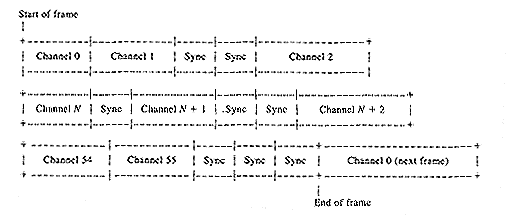
Frame Format: each frame consists of 56 channels, which are numbered from 0 to 55. The channels are consecutive within the frame, starting with channel 0. The frame format is shown in Fig. 2.

Figure 2 - Frame format of MADI
Channel Format: each channel consists of 32 bits, of which-24 are allocated to audio or to other data as defined by the audio/nonaudio status flag. A further 4 bits represent the validity (V), user (U), status (C), and parity (P) bits of the two-channel AES3-1985 interface, with a further 4 bits allocated for mode identification. In this manner, the two-channel format of AES3-1985 is preserved. The channel format is shown in Fig. 3.

Figure 3 - Channel data format of MADI
Mode Bits: the mode bits provide for frame synchronization, for block start per AES3-1985, for identification of the A and B subframes also present in AES3-1985, and for active/inactive status per channel.
Audio Data Representation: in the audio mode, the 24-bit format is represented linearly in 2's complement form, with the most significant bit (MSB) transmitted last. All unused audio bits within a channel shall be set to zero, with the V, U, C, and P bits set to default values, as defined by the AES3-1985 twochannel format.
Active Channels: all active channels shall be consecutive, starting at channel zero. The channel active bit must be set to 1 within each active channel.
Inactive Channels: all inactive channels shall have all bits set to zero, including the channel active bit. Inactive channels shall always have a higher channel number than the highest numbered active channel.
Bit Description: see Tables I and II.

Table I

Table II
Transmission Format: the 56 channels are transmitted serially by non-return-to-zero inverted (NRZI) polarity-free coding, using a 4-bit to 5-bit encoding format (as proposed in document 84-48 of American National Standards Institute accredited Standards Committee X3, Subcommittee T9.5).
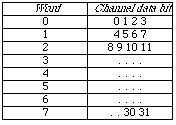
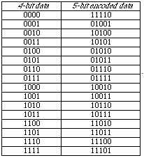
Encoding Scheme: for the purposes of encoding, the 32-bit channel data are broken down into 8 words of 4 bits each, as shown in Table III. Each 4-bit word is encoded into a 5-bit word, as shown in Table IV. Each 5-bit encoded word is transmitted from the left, as defined in Table V. This scheme enables a low direct-current (dc) bias to be maintained on the link. Although the link signal is nearly dc free, the audio signal may contain direct current. Fig. 4 shows the link transmission format for one channel. For the purposes of clarity, the ending example illustrates the encoding process for a single-channel word.

Table III

Table IV

Figure 4 - Channel link format of MADI
Synchronization Symbol: a synchronization symbol, 11000 10001, shall be inserted into the data stream at least once per frame period to ensure transmitter and receiver synchronization. Sufficient synchronization symbols shall be inserted by interleaving with the encoded data words to fill the total link capacity. The synchronization symbol is transmitted from the left. The synchronization symbol may only be inserted at 40-bit channel boundaries, but may be repeated between channels or during the idle period or both after the last channel has been transmitted in each frame capacity. The order placement of synchronization signals is not specified. Some examples of permissible positions of the synchronization symbol are shown in Fig. 5.

Figure 5 - Some permissible synchronization symbol positions of MADI
Sequence of Transmission: in any bit sequence, the left-hand symbol always represents the first in time.
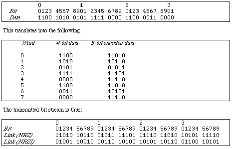
NRZI Encoding: the link channel data are transmitted using an NRZI polarity-free encoding. Each high bit of the NRZ data is converted to a transition from the last bit; each low bit is represented by no transition. Therefore a 1 results in a high-to-low or a low-to-high transition, and a 0 results in a static high or a static low.
Sample Frequency and Rates
Sample Frequency: the nominal sample frequency at which the link operates is within the range of 32.0 kHz to 48.0 kHz. In addition, the facility to operate at +-12.5% of these frequencies is provided. Higher sample frequencies may be accommodated (e.g., 96 kHz) by using two or more channels per audio sample on the link.
Link Transmission Rate: the link transmission rate shall be 125 megabits per second irrespective of the sample rate or number of active channels.
Data Transfer Rate: the data transfer rate shall be l00 megabits per second. The difference between the data transfer rate and the link transmission data rate is due to the use of an encoding scheme (see the Encoding Scheme definition above).
Maximum Used Data Rate: the provision of 56 channels at 48 kHz +-12.5% gives a maximum used data rate of 96.768 megabits per second.
Minimum Used Data Rate: the provision of 56 channels at 32 kHz +-12.5% gives a minimum used data rate of 50.176 megabits per second.
Synchronization
This section covers the synchronization of transmitters and receivers relative to a master synchronizing signal. It does not apply in the case of a master-slave connection only.
Synchronizing Signal: each transmitter and receiver shall be provided with an independently distributed master synchronizing signal. This signal shall be in accordance with AES3-1985.
Sample Timing: the link is not intended to carry sample timing information. The exact timing of connected equipment is controlled by the independently distributed master synchronizing signal, not by the multichannel audio digital interface.
Transmitted Frame Start Time: the frame start time output from a transmitter shall be within +-5% of a sample period of the reference time defined by the transmitter's externally supplied master synchronizing signal.
Received Frame Start Time: a receiver shall be able to interpret correctly a signal whose frame start time is within +-25% of a sample period of the reference time defined by the receiver's externally supplied master synchronizing signal.
Electrical Characteristics
The transmission medium shall be either 75-ohm coaxial cable or fiber optic. For the purposes of transmission characterization, the data input to the encoder shall be replaced with a pseudorandom data generator having a sequence length of at least [2^(16)-1]. Note that the random data are applied prior to the 4-bit to 5-bit encoder in order to represent accurately those signals most likely to appear in normal transmission.
For the Coaxial Cable and Fiber Optic detailed description see the original AES specification document.
Example of Link Encoding
Suppose the channel data word is as follows:

[Index |
Main Paragraph |
Previous Paragraph |
Next Paragraph ]